
In our important role as hydraulic pump manufacturers, we are aware of the large number of variables that need to be considered when choosing the right pump for the specific application. The purpose of this first article is to begin to shed light on the large number of technical indicators within the hydraulic pump universe, starting with the parameter “pump head”.
What is the pump head?
The head of a pump is a physical quantity that expresses the pump’s ability to lift a given volume of fluid, usually expressed in meters of water column, to a higher level from the point where the pump is positioned. In a nutshell, we can also define head as the maximum lifting height that the pump is able to transmit to the pumped fluid. The clearest example is that of a vertical pipe rising directly from the delivery outlet. Fluid will be pumped down the pipe 5 meters from the discharge outlet by a pump with a head of 5 meters. The head of a pump is inversely correlated with the flow rate. The higher the flow rate of the pump, the lower the head.
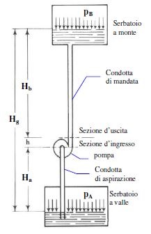
In the operating diagram of a pumped water lifting system with references for calculating the head (1) suction pipe (2) delivery pipe is defined as:
- geodetic suction height Ha: the difference in level between point A and the pump
- geodetic delivery height Hm: the difference in level between point B and the pump
- geodetic head H: the difference between liquid levels at discharge and suction
The geodetic head H, commonly referred to as head, is therefore the sum of the suction and discharge geodetic heights Ha and Hm.
 Pumps play a fundamental role in transferring fluids.
There are two main factors in determining the size of the pump:
- Flow rate, the quantity of fluid (or volume) that goes through the pump in a specific unit of time.
- Hydraulic head of a pump, the actual energy that the pump can deliver to the fluid
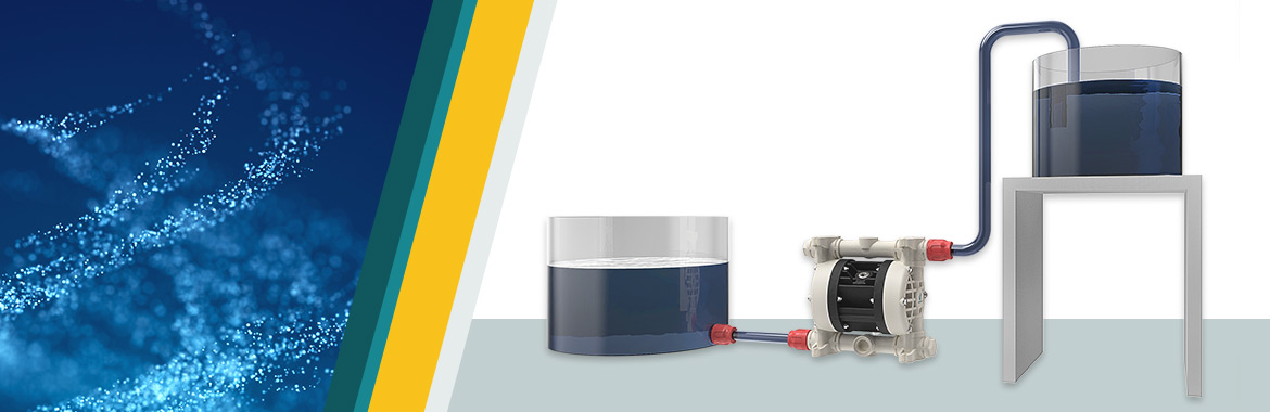
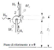
By examining a generic system like the one shown in the adjacent figure, there are two fundamental measurements:
- Hg geodetic head
- Ha head in the suction duct
- Hb head in the delivery duct
- h difference in height between the inlet and outlet of the pump
- pa pressure on the downstream tank
- pb pressure on the upstream tank
Calculating the head of a pump: bernoulli’s principle
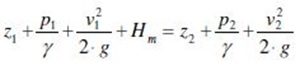
What is the head of a pump? As mentioned earlier, the head corresponds to the actual energy that the pump delivers to the fluid. The Bernoulli equation is applied between the pump’s inlet and outlet sections:
H1 + Hm = H2 H1 = inlet energy
Hm = energy delivered by the pump
H2 = outlet energy
Replacing with Bernoulli’s equation:
The term that we normally want to find is Hm.
However, during the design stage, P1 and P2 are never known (as there is no physical element yet and therefore it is not possible to effectively measure the pump’s inlet and outlet pressure).
Therefore two new terms are defined, which are known, and which allow us to overcome the problem and determine the size of the pump:
P1 = Pa – γ * Ha
P2 = Pb + γ * Hb
Considering, moreover, that:
Hg = h + Ha + Hb
Which gives us a relation defined as follows:
![]()
Calculating the head loss for a pump
In a real situation we must also consider the head loss due to the fluid flowing through the ducts and in the various construction parts, in suction and delivery (valves, curves, fittings, etc.).
The equation is defined as follows:
![]()
Now we will examine a more complex issue, that is the calculation of the last term of the aforementioned equation, which represents the total of the losses distributed along the pipes (suction and delivery) and the concentrated losses (valves, curves, etc.).
Distributed head losses
As the fluid flows inside a pipe it loses energy (deducible in terms of pressure) due to the friction between the fluid and the walls of the pipe.
These losses depend on the characteristics of the pipe and a re proportional to its length.
In order to calculate them we must define a friction factor, which depends on the speed of the fluid.
There are two different cases: laminar flow and turbulent flow.
1. Laminar flow
The flow of the fluid is laminar, or Reynolds < 2000.

Ρ = fluid density
W = fluid speed
D = fluid diameter
µ = fluid viscosity
where the speed can be deduced by knowing the flow rate necessary for the size and therefore from the following formula:
w = (4*Q)/(π*D2)
The friction factor in this type of flow is defined as follows:
Fa = 64/Re
Therefore to calculate the continuous losses expressed in metres, in laminar flow, we will proceed as follows:
Yc = (Fa/ γ) *(L/D) * w2/2
2. Turbulent flow
The flow of the fluid is turbulent, or Reynolds > 4000, (most common case).
Taking into account the formulas used to calculate the speed and the Re number, the resulting friction factor will be:
Fa = 0.07 * Re-0.13 * D-0.14
And the head losses in the turbulent flow will be:
Yc = (Fa/ γ) *(L/D) * w2/2
Concentrated head losses
Along the pipes of a system there are numerous construction and management elements such as valves, fittings, narrowing, etc., that contribute to head loss.
There are different methods for calculating these head losses.
The simplest and easiest to understand is by using the following diagram.
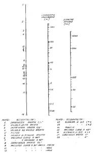
- The axis on the right represents the internal diameter of the pipe expressed in mm.
- The axis on the left represents the different obstacles along the pipe.
- The axis in the middle is the corresponding head loss expressed in metres, relative to the element in question (e.g. valve), along a pipe with an internal D of 50 mm.
At this point we can easily calculate the head losses of the system, and therefore choose the correct size of the pump to achieve the desired flow rate at the resulting equivalent head.

Where can I find the pump head figure?
The pump head indicator is present and can be found in the data sheets of all our main products. To obtain more information on the technical data of our pumps, please contact the technical and sales team.