
Hydraulic pumps are operating machines that move volumes of fluid continuously and/or discontinuously.
The pump supplies MECHANICAL ENERGY to a fluid, which can be:
Kinetic energy – to make the fluid acquire speed, and which therefore influences the flow rate.
Pressure energy – which can further be:
- Geodetic: to lift the fluid to height.
- Piezometric: to overcome pressure differences in the pipes.
Hydraulic pumps can be of various types according to the most varied conditions of use, depending on the type of fluid to be used, operating pressures, temperatures and system characteristics.
Pumps are classified according to their operating principle and construction characteristics.
The macro categories are subdivided into:
- Volumetric pumps: reciprocating pumps (piston or diaphragm), rotary pumps (gear pumps, lobe pumps, capsule pumps, vane pumps, deformable vane pumps, eccentric screw pumps, elliptical rotor pumps.
- Kinetic pumps: Centrifugal (single-impeller, multi-impeller), Turbines (axial-flow, mixed-flow).
- Special pumps: Peristaltic, Liquid Piston, Archimedes Screw, Air Lift or Mammoth, Ejectors, Liquid Mounters.
The use of hydraulic pumps in history
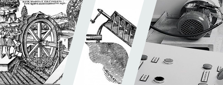
Hydraulic pumps first appeared in the third century B.C. thanks to Archimedes, who designed the pump known as the Archimedes Screw: this device could move large quantities of fluid at low heads. The Archimedes Screw is still used today, especially in the water purification sector.
In the same historical period, the Noria pump made its appearance: this is a mechanism capable of lifting fluids at higher heads, up to 20/30 meters. The operation is typical of a mill, where a watercourse acts as a source of fluid and mechanical energy. The fluid was lifted by means of cup-shaped vessels.
Around 1600, the invention of the first rod-crank systems enabled the creation of the first piston pumps, driven by the strength of the arms. The advent of steam and its use as a motive power source made it possible to technologically improve this type of pump, which began to be able to lift fluids to considerable depths, so much so that they were also used in mines to drain underground wells.
Over the years, technological progress allowed the creation of systems capable of moving large quantities of fluid at ever higher heads: the use of internal combustion engines and later electric motors allowed the development of rotary machines that transformed kinetic energy into pressure.
Technical background on hydraulic pumps
As we have seen, hydraulic pumps are subdivided into three distinct categories, so let us take a closer look at each type in detail:
Reciprocating pumps
Reciprocating (or piston) pumps are characterised by the alternating rectilinear motion of a moving organ, the piston. This exerts pressure on the fluid, transferring energy to it. This type of pump is suitable for developing very high heads the pump capacity depends on the size and speed of rotation of the system.
Reciprocating pumps can be further classified into two types:
- Plunger pumps: characterised by an architecture in which the movement of the fluid is essentially caused by a piston connected to a connecting rod-crank system.
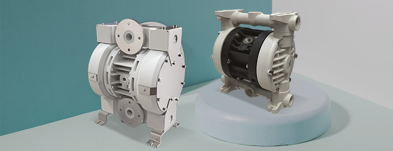
- Diaphragm pumps: characterised by an architecture within which the fluid is moved by membranes set in motion by air or other systems.
Examples of reciprocating pumps are the fuel injection pumps of modern diesel engines.

Centrifugal pumps
Centrifugal pumps consist of a chamber with an increasing cross-section, called a scroll or diffuser, connected at the centre with the suction pipe and at the periphery with the discharge pipe. Inside the scroll, a rotating organ, called an impeller or impulsor, turns at high speed (1500 to 3000 rpm). The liquid contained within the volute, due to the high angular velocity transmitted by the impeller, is pushed by centrifugal force towards the periphery and consequently a depression is created in the centre; thus, part of the kinetic energy is transformed into pressure energy, conveying the liquid into the delivery pipe and creating a depression in the centre of the pump which will draw more liquid from the suction pipe.
Centrifugal pumps are essentially composed of:
- Distributor: a fixed organ through which the liquid to be pumped enters in an axial direction and is sent to the impeller.
- Diffuser: also known as the scroll, a fixed element that transforms the kinetic energy accumulated by the liquid into pressure energy (by gradually increasing the cross-sectional area of this organ), thus conveying the liquid in a radial direction towards the delivery pipe.
- Impeller: This is a rotating organ, with a different shape and profile, engaged on the motor shaft from which it receives the energy to impart to the liquid. The impeller is the main element of the pump, consisting of a series of vanes whose curvature must be such as to satisfy two requirements (hydraulic aphorisms) to minimise the pump’s pressure losses:
The inlet of the liquid into the pump must be shock-free
The exit of the liquid into the pump must take place with the lowest possible speed
It is possible to choose between different impeller models, depending on the required head and the type of fluid to be moved:
- Radial flow impeller: consisting of a series of blades fitted between two discs keyed to the pump shaft, with a narrow or wide channel and straight or curved blades.
- Open impeller: with helical blades splined directly onto the hub, suitable for conveying liquids with suspended solid particles.
Centrifugal pumps, when there is a need to overcome high heads while still maintaining high flow rates, can be multi-impeller. In these, several impellers are connected to the same shaft. The internal geometry forces the liquid leaving one impeller to enter the next. The pump thus functions as several pumps in series, but with greater compactness. There are both horizontal-axis and vertical-axis pumps on the market. The latter can be used when the space available for installation is very small, as the motor is placed right above the pump. A particular type of vertical-axis pump is the submersible pump, in which the electric motor is placed inside an airtight container. These pumps can, therefore, be installed below the liquid level and are therefore used to pump water from particularly deep wells or underground tanks. Centrifugal pumps can also be self-priming, these pumps are capable, unlike normal centrifugal pumps, of sucking in the air contained in the suction line and creating a vacuum inside the pump that ensures the suction of the liquid to be pumped. These pumps are single-impeller pumps, have a good head, but generally have a lower efficiency than normal centrifugal pumps, due to the recirculation of part of the pumped liquid. Depending on the technical arrangements and mechanical solutions adopted, they can essentially be of two types:
- Side-channel self-priming centrifugal pumps: They have a separate chamber in the outermost part, which is divided into two sectors that identify the suction chamber and the delivery chamber. In the central area of the two chambers, there is a suction light and a discharge light respectively. To the rear of this outer chamber is a chamber in which an open, star-shaped impeller rotates, rotating with a minimum of play, to ensure a high priming capacity, i.e., it works in contact with the pump body and breech, thus creating a vacuum that draws the liquid from the suction chamber through the inlet port to the discharge port and then to the discharge chamber. In one or both walls of the chamber or on the face of the rotor, the pump is fitted with a circular groove, suitably shaped in the form of a channel, which causes a secondary circulation of liquid between the impeller and side channels.
- Centrifugal self-priming liquid ring pumps, these pumps are equipped with an open star impeller, rotating eccentrically within the pump chamber; the rotation of the impeller causes the liquid to be pumped to thicken at the periphery of the chamber, forming a liquid ring that will fill the space delimited between the impeller vanes, driving out all the air; in this way, a progressive vacuum is created that produces the suction of the liquid.
The main uses of centrifugal pumps include pumping chemicals, water, in agriculture, electroplating, fume abatement towers and in the petrochemical industry. Centrifugal pumps are often chosen for their high flow capacity, compatibility with abrasive solutions, mixing potential and relatively simple engineering.

Rotary pumps
Rotary pumps are characterised by the slow rotary motion of moving parts: gear wheels or lobes. Energy is transferred by exerting pressure on the fluid in a similar way to piston pumps. The operation of a rotary pump requires that a fixed volume of fluid is moved for each rotation. These pumps are self-priming and provide an almost constant flow rate regardless of pressure. Rotary pumps are designed with very small distances between the rotating and stationary parts to minimise losses from the delivery side to the suction side.
Rotary pumps can be further classified into three types according to the type of moving parts with which they are constructed:
- Gear pumps that utilise the movement of gears to pump fluid by displacement. They are one of the most common types of pumps for hydraulic power applications.
- Lobe pumps like gear pumps, except that the lobes are designed so that they meet, rather than touch and turn with each other.
Rotary pumps are commonly used to circulate lubricating oil in mechanical equipment or to provide pressure to hydraulic operating systems.