

This type of pump is used for fluids that cannot be significantly compressed.
The working fluid is processed by the machine in a control volume that varies over time periodically.
The work is exchanged statically with the machine, on moving surfaces.
The volumetric pumps may be:
- alternating;
- rotatative.
based on whether the movement is transmitted by a mechanical part in an alternating or rotating way.
They quantity of fluid pumped depends of various factors.
mt : theoretical mass of fluid transferred (depends on the volume of the chamber in which the fluid enters)
λv : volumetric filling coefficient, given by the relation between the suction fluid mass ma and theoretical mass mt
λp : loss coefficient, given by the relation between fluid mass in delivery mm and suction mass ma
The final efficiency of fluid mass in delivery will therefore be:
ηv volumetric efficiency, produced between λv * λp.
Alternating volumetric pumps are usually piston pumps and they can be classified according to the type of piston:
- plunger;
- disc or diaphragm.
These can be further divided into:
- single effect (the complete cycle includes a suction and a delivery);
- double effect (for each cycle there are, alternating, two suctions and two deliveries).
Single effect
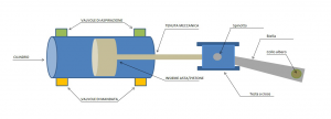
Double effect
WORK CYCLE
Let’s examine the ideal work cycle of an alternating volumetric pump, without any leaks of any kind inside the pump.
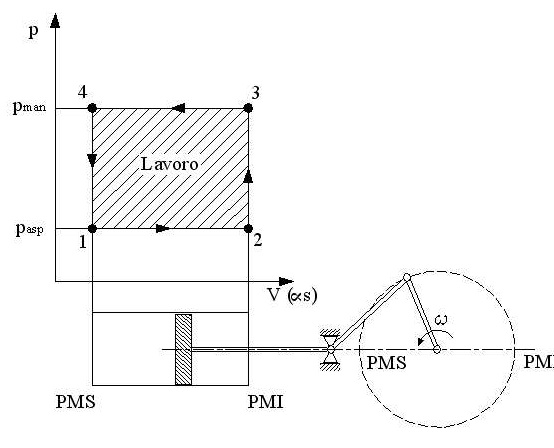
Ideal work cycle:
Phase 1-2: the fluid is drawn inside the chamber
Phase 2-3: there is an instantaneous compression
Phase 3-4: the fluid is pushed through the delivery duct
Phase 4-1: instantaneous expansion (decompression phase)
In actual fact the cycle is as follows.
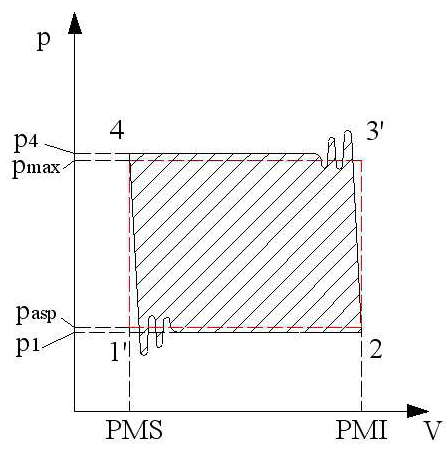
Actual work cycle:
As can be seen in the figure, the actual cycle differs from the ideal one due to certain effects that cannot be ignored.
In particular:
- In the suction and delivery phases the volume fluctuates due to possible leakages between the various mechanical parts and in the non-instantaneous opening/closure of the valves;
- In the compression and expansion phases there is a drop in pressure as the fluid manifests its compressibility, however slight. Moreover gases may be dissolved in the fluid or there may be air bubbles that contribute to the compressibility of the volume;
- As it is an alternating machine the speed of the fluid in the ducts changes suddenly and this causes continuous peaks of pressure.
There are solutions that can limit these effects:
- To overcome the presence of air bubbles simply degas the liquid and keep the suction hoses full of liquid as much as possible;
- To limit drops in pressure due to the discontinuity of the flow rate, compensators can be installed upstream and downstream of the pump, to overcome this fluctuation during the suction/delivery phase.
- Rubber gaskets are used on machines to improve the seal and decrease leaks.
FLOATING VOLUME PROBLEM
As mentioned earlier, one of the main problems of alternating volumetric pumps is the irregular flow rate.
In fact, seeing as, in both piston pumps and in diaphragm pumps, the speed at which the mechanical part that provides the thrust varies over time (Vs(t)), the instantaneous volumetric flow rate (Qis) of the pump will also vary.
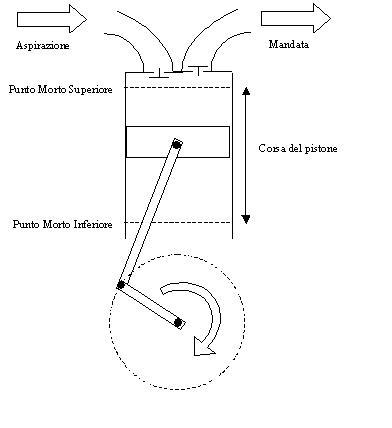
For simplicity’s sake let’s examine an alternating piston pump with a cylindrical shape, with an ordinary crank gear.
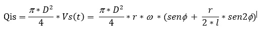
The performance of the volumetric flow rate over time will therefore have the shape shown in figure a).
One of the simplest solutions to regulate the flow and eliminate the moments when the flow rate drops to zero, is to increase the number of pistons (graph b) and c)), or in the same way, increase the effects of the single piston (graph b), double acting single cylinder pump).
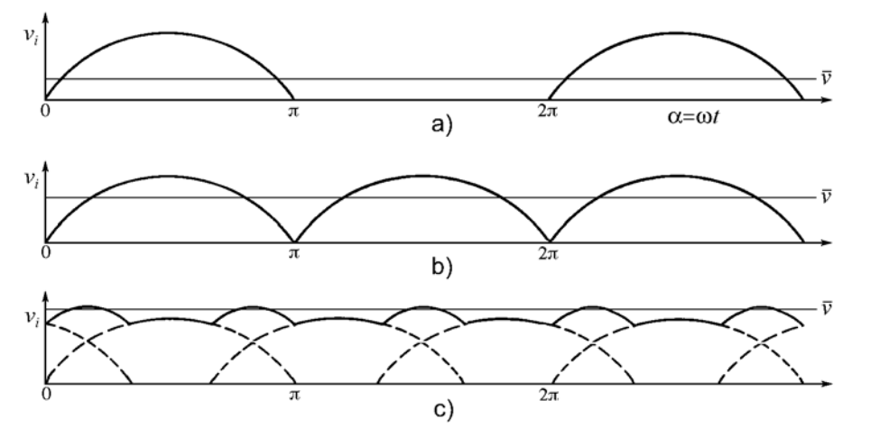 Flow rate performance for single, twin and three cylinders.
Using a pump with various cylinders or a double acting cylinder reduces problems due to the pulsations on a pumping system.
AIR CHAMBERS
To regulate the volumetric flow rate, compensators are used along the suction and delivery line.
They are half-filled with the working fluid whilst the upper part is filled with gas (often air).
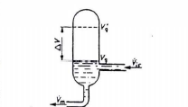
Air chambers
Using the flow rate performance graphs, there are two phases during the piston cycle:
- When Qis exceeds the average flow rate (marked on the graph), the tank fills;
- When Qis drops below the average flow rate, the tank returns the accumulated fluid.
In this way there will be a fairly constant flow rate in the ducts.
This mechanism is accelerated thanks to the gas contained in the compensator that, by compressing and expanding, reduces the pulsation of the fluid flow.